All About TL594: Features, Design, and Uses
The TL594 is a reliable device designed for pulse-width modulation control. It simplifies complex tasks like signal timing and power management, making it a versatile choice for various circuit applications. With features like error amplifiers, adjustable oscillators, and dead-time control, it provides efficient and adaptable performance. Whether you're managing power supplies or fine-tuning circuit behavior, this device offers an easy-to-use solution.Catalog
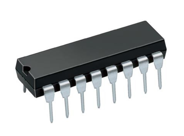
Overview of TL594
The TL594 is a versatile device designed to meet the needs of pulse-width-modulation (PWM) control circuits. It's often used in power-supply designs, offering engineers the flexibility to adapt its control functions for specific purposes. Packed with features like error amplifiers, an adjustable oscillator, and a dead-time control comparator, it handles complex tasks efficiently.
Its error amplifiers work within a specific voltage range, ensuring stable performance. The on-chip oscillator adds convenience by allowing both master and slave operations, while the dead-time control ensures optimal performance by managing signal timing. With output options for either push-pull or single-ended configurations, it can cater to a variety of setups.
This device is also designed to lock its outputs until all internal systems are functioning correctly, enhancing reliability. With its robust build and temperature-based variants, the TL594 is suitable for a wide range of applications, offering reliable performance in demanding environments.
TL594 Pin Configuration
[IMAGE OF TL594 Pin Configuration]
TL594 CAD Model
TL594 Symbol
[IMAGE OF TL594 Symbol]
TL594 Footprint
[IMAGE OF TL594 Footprint]
TL594 3D Model
[IMAGE OF TL594 3D Model]
Features of TL594
Complete Pulse Width Modulation Control Circuit
The TL594 is designed to offer a complete pulse-width modulation control system, making it versatile for a variety of applications. This feature ensures that you have the flexibility to manage timing and signal output effectively within your circuit.
On-Chip Oscillator with Master or Slave Operation
With an on-chip oscillator, the TL594 allows you to choose between master and slave operations. This adaptability makes it easy to integrate the device into different setups, ensuring smooth and synchronized performance for your design.
On-Chip Error Amplifier
The built-in error amplifier helps maintain accuracy by correcting any deviations in your circuit. This means you can rely on consistent performance and avoid unnecessary disruptions during operation.
On-Chip 5.0 V Reference Voltage Source with 1.5% Accuracy
The TL594 includes a precise 5.0 V reference voltage source with an impressive 1.5% accuracy. This feature ensures that your system remains stable, delivering reliable voltage outputs for sensitive components.
Adjustable Dead Time Control
This device allows you to adjust the dead time, giving you control over the timing between signals. This feature is particularly useful when optimizing circuit performance to prevent overlap or interference.
Non-Dedicated Output Transistor with Rated Output Current
Equipped with a non-dedicated output transistor, the TL594 can handle a rated output current of up to 500 mA, whether sourcing or sinking. This capability ensures that it can manage a range of output requirements with ease.
Output Control for Push-Pull or Single-Ended Operation
The TL594 offers output control options, allowing you to choose between push-pull and single-ended configurations. This flexibility ensures that the device can meet the specific needs of your project, no matter the setup.
Undervoltage Lockout
To enhance reliability, the TL594 features an undervoltage lockout mechanism. This ensures that the device only operates when internal conditions are fully ready, protecting your circuit from potential issues caused by insufficient voltage.
Lead-Free Packaging
The TL594 comes with lead-free packaging, making it an environmentally friendly choice. You can confidently use this device while adhering to modern environmental standards.
TL594 Specifications
Technical specifications, features, characteristics, and components with comparable specifications of Texas Instruments TL594.
[TABLE OF Specifications]
Functional Block Diagram of TL594
[IMAGE OF TL594 Functional Block Diagram]
Circuit Design of TL594
[IMAGE OF TL594 Circuit]
Amplifier Characteristics Test Circuit for TL594
[IMAGE OF Amplifier-Characteristics Test Circuit]
Operational Test Circuit and Waveforms for TL594
[IMAGE OF Operational Test Circuit and Waveforms]
TL594 Mechanical Details
[IMAGE OF TL594 Mechanical Data]
Manufacturer Information of TL594
Texas Instruments, the company behind the TL594, is a leading technology manufacturer based in Dallas, Texas. They specialize in designing and producing semiconductors and integrated circuits for various industries worldwide. Known for their innovative approach, they focus heavily on analog chips and embedded processors, which form a major part of their business.
The company also creates other advanced technologies like digital light processing systems and educational tools, including calculators and microcontrollers. With a global presence and decades of expertise, Texas Instruments continues to support engineers and designers with high-quality products. Their extensive portfolio and dedication to innovation have made them a trusted name in the electronics industry.
Frequently Asked Questions [FAQ]
1. What makes TL594 different from TL494?
The TL594 and TL494 are both PWM controllers, but they differ in a few areas. The TL594 operates at a higher switching frequency of 300kHz compared to 200kHz for the TL494. Additionally, the TL594 has a reference voltage accuracy of 1%, providing more precision in voltage regulation, while the TL494 offers 5% accuracy. The TL594 also includes a feature to lock outputs during low voltage conditions, which enhances reliability in sensitive applications.
2. Are there other PWM power control chips like the TL594?
Yes, there are several PWM control chips available, but the TL594 stands out for its versatility and features. It has 16 pins and can manage a range of functions, including adjustable dead time, push-pull operation, and reliable voltage control. These capabilities make it a suitable choice for various power management and circuit control applications.
3. How does the TL594 work?
The TL594 generates square wave signals with a fixed frequency and an adjustable pulse width through its output terminals, Q1 and Q2. The frequency is determined by external components connected to the RT and CT pins, calculated using the formula f = 1.1/(RT × CT). The pulse width is controlled by a signal from the flip-flop module, which is influenced by comparators like the dead-time comparator, pulse-width modulation comparator, and undervoltage lockout comparator. These components work together to ensure stable, reliable operation, with only one output pulse generated at a time to maintain precision.
Om os
ALLELCO LIMITED
Læs mere
Hurtig forespørgsel
Send en forespørgsel, vi svarer med det samme.
Ofte stillede spørgsmål [FAQ]
1. What makes TL594 different from TL494?
The TL594 and TL494 are both PWM controllers, but they differ in a few areas. The TL594 operates at a higher switching frequency of 300kHz compared to 200kHz for the TL494. Additionally, the TL594 has a reference voltage accuracy of 1%, providing more precision in voltage regulation, while the TL494 offers 5% accuracy. The TL594 also includes a feature to lock outputs during low voltage conditions, which enhances reliability in sensitive applications.
2. Are there other PWM power control chips like the TL594?
Yes, there are several PWM control chips available, but the TL594 stands out for its versatility and features. It has 16 pins and can manage a range of functions, including adjustable dead time, push-pull operation, and reliable voltage control. These capabilities make it a suitable choice for various power management and circuit control applications.
3. How does the TL594 work?
The TL594 generates square wave signals with a fixed frequency and an adjustable pulse width through its output terminals, Q1 and Q2. The frequency is determined by external components connected to the RT and CT pins, calculated using the formula f = 1.1/(RT × CT). The pulse width is controlled by a signal from the flip-flop module, which is influenced by comparators like the dead-time comparator, pulse-width modulation comparator, and undervoltage lockout comparator. These components work together to ensure stable, reliable operation, with only one output pulse generated at a time to maintain precision.
Udforskning af BMP280 -sensoren
på 2024-11-20
TPS1H100BQPWPRQ1 High-Side Strømafbryder: Datablad, layout og pinout
på 2024-11-20
Populære indlæg
-

Hvad er GND i kredsløbet?
på 1970-01-01 3317
-

RJ-45 Connector Guide: RJ-45 Stikfarvekoder, ledningsordninger, R-J45-applikationer, RJ-45 datablad
på 1970-01-01 2842
-

Forståelse af strømforsyningsspændinger i elektronik VCC, VDD, VEE, VSS og GND
på 0400-11-21 2746
-

Fiberstikstyper: SC vs LC og LC vs MTP
på 1970-01-01 2277
-

Sammenligning mellem DB9 og RS232
på 1970-01-01 1897
-
Hvad er et LR44 -batteri?
Elektricitet, den allestedsnærværende kraft, roligt gennemsyrer alle aspekter af vores daglige liv, fra trivielle gadgets til livstruende medicinsk udstyr, det spiller en stille rolle.Imidlertid er det ingen let opgave at gribe ind i denne energi, især hvordan man opbevarer og effektivt udsender den.Det er på denne baggrund, at denne artikel vil fokusere på en type møntcellebatteri, der kan ...på 1970-01-01 1856
-

Hvad er RF, og hvorfor bruger vi det?
Radiofrekvens (RF) -teknologi er en vigtig del af moderne trådløs kommunikation, der muliggør datatransmission over lange afstande uden fysiske forbindelser.Denne artikel dækker det grundlæggende i RF og forklarer, hvordan elektromagnetisk stråling (EMR) gør RF -kommunikation mulig.Vi vil udforske principperne for EMR, oprettelse og kontrol af RF-signaler og deres omfattende anvendelser.Art...på 1970-01-01 1837
-

Forståelse af de grundlæggende elementer: induktansresistens, og kapacitet
I den komplicerede dans inden for elektroteknik tager en trio af grundlæggende elementer centrum: induktans, modstand og kapacitans.Hver bærer unikke træk, der dikterer de dynamiske rytmer af elektroniske kredsløb.Her går vi på en rejse for at dechiffrere kompleksiteten af disse komponenter for at afsløre deres forskellige roller og praktiske anvendelser inden for det store elektriske o...på 1970-01-01 1826
-

CR2430 Batteri Comprehensive Guide: Specifikationer, applikationer og sammenligning med CR2032 -batterier
Hvad er CR2430 -batteri?Fordele ved CR2430 -batterierNormCR2430 Batteri applikationerCR2430 ækvivalentCR2430 vs CR2032Batteri CR2430 størrelseHvad man skal kigge efter, når man køber CR2430 og ækvivalenterDatablad PDFOfte stillede spørgsmål Batterier er hjertet i små elektroniske enheder.Blandt de mange tilgængelige typer spiller møntceller en afgørende rolle, der ofte findes i regnemas...på 1970-01-01 1820
-
Omfattende guide til HFE i transistorer
Transistorer er afgørende komponenter i moderne elektroniske enheder, hvilket muliggør signalforstærkning og kontrol.Denne artikel dækker i viden omkring HFE, herunder hvordan man vælger en transistors HFE -værdi, hvordan man finder HFE og gevinsten af forskellige typer transistorer.Gennem vores udforskning af HFE får vi en dybere forståelse af, hvordan transistorer fungerer og deres rolle...på 5600-11-21 1818
